Automotive Engines : Diagnosis, Repair, Rebuilding: Most of today’s automobiles and light trucks are powered by a Spark-Ignited four stroke reciprocating Engine. The first Engine of this type was built in 1876 by Nicolaus Otto in Germany.
 |
| Automotive Engines : Diagnosis, Repair, Rebuilding |
Automotive Engines : Diagnosis, Repair, Rebuilding Handbook
CONTENTS of Automotive Engines : Diagnosis, Repair, Rebuilding handbook:
- Capter 1 Engine Operation .
- Capter 2 Engine Shop Safety .
- Capter 3 Diagnosing Engine Problems .
- Capter 4 Engine Removal , Disassembly , Inspection , and in -Chassis Repairs .
- Capter 5 Cleaning the Engine .
- Capter 6 Measuring .
- Capter 7 Cylinder Head : Springs , Valves , and Valve Seats .
- Capter 8 Camshafts , Lifters, Timing Belts , and Chains .
- Capter 10 Engine Power and Performance .
- Capter 11 Cylinder Block : Inspection and Service .
- Capter 12 Crankshaft , Bearings, and Engine Balancing .
- Capter 13 Pistons , Rings , and Connecting Rods .
- Capter 14 Lubrication .
- Capter 15 Cooling System .
- Capter 16 Engine Hardware : Fasteners , Thread Repair , and Gaskets .
- Capter 17 Reassembly and Starting .
Capter 1 Engine Operation .
- Simple Engine
- Four Stroke Engine Operation
- Cylinder Arrangement
- Valvetrain
- Cylinder Block
- Front-Wheel Drive
- Engine Classifications
- Combustion Chamber Designs
- Direction of Crankshaft Rotation
- Firing Order
- Engine Cooling
- Spark and Compression Ignition
- Putting It All Together
- High-Performance Engine Trivia.
INTRODUCTION
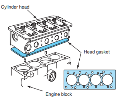
A simple reciprocating engine has a cylinder, a piston, a connecting rod, and a crankshaft. The cylinder can be compared to a cannon and the round piston can be compared to a cannonball. The end of the cylinder is sealed with a cylinder head. The piston, which is sealed to the cylinder wall by piston rings, is connected to the crankshaft by a connecting rod and a piston pin (also called a wrist pin). This arrangement allows the piston to return to the top of the cylinder, making continuous rotary motion of the crankshaft possible. Because of the powerful impulses on the piston as the fuel is burned in the cylinder, a heavy flywheel is bolted to the rear of the crankshaft (Figure 1.2). The weight of the flywheel blends the power impulses together into one continuous motion of the crankshaft. The cylinder head has one combustion chamber for each cylinder (Figure 1.3). An intake valve port allows a mixture of air and fuel to flow into the cylinder, and an exhaust valve port allows the burned gases to flow out. Each port is sealed off by a poppet style valve. The head is sealed to the cylinder block with a head gasket (Figure 1.4). The opening of the valves is controlled by the camshaft (Figure 1.5). Automotive Engines.
- Intake Stroke. Gasoline will not burn unless it is mixed with the correct amount of air. It is very explosive when 1 part is mixed with about 15 parts of air. Shortly before the piston reaches TDC, the intake valve begins to open. As the crankshaft turns, it pulls the rod and piston down in the cylinder toward BDC (Figure 1.6).
- Compression Stroke. The piston moves up in the cylinder, compressing the air-fuel mixture ( Figure 1.7). If you light a puddle of gasoline on fire in open air it does not produce power. If it is confined in a cylinder, however, usable power can be produced. Compressing the mixture of air and fuel into a smaller area makes it easier to burn. The compression stroke begins at BDC after the intake stroke is completed. As the piston moves toward TDC, both of the valves are closed as the mixture is compressed to about 1⁄8 of the volume it occupied when the piston was at BDC. In this case, the compression ratio is said to be 8:1 (Figure 1.8). If the mixture is
- compressed to 1 ⁄12 its original volume, the compression ratio is then 12:1.
- Power Stroke. As the piston approaches TDC on its compression stroke, the compressed air-fuel mixture becomes very explosive (Figure 1.9). When the ignition system generates a spark at the spark plug, the fuel ignites. The air-fuel mixture burns, but it must not explode. As the mixture burns it expands, forcing the piston to move down in the cylinder until it reaches BDC ( Figure 1.10). The action of the piston turns the crankshaft to power the car. The power stroke is sometimes called the expansion stroke. Some leakage of gases past the rings occurs during the power stroke. This leakage, called blowby, causes pressure in the crankcase ( Figure 1.11).
- Exhaust Stroke. As the piston nears BDC on the power stroke, the exhaust valve opens, allowing the spent gases to escape. Because the burning gases are still expanding, they are forced out through the open exhaust valve. As the crankshaft continues to turn past BDC, the piston moves up in the cylinder, helping to push the remaining exhaust gases out through the open exhaust valve (Figure 1.12). A few degrees after the piston passes TDC, the exhaust valve closes. The entire four stroke cycle repeats itself, starting again as the piston moves down on the intake stroke The four stroke cycle is considerably more complicated than this simple explanation. When the engine is running, the timing of the opening and closing of the valves actually determines when each stroke effectively begins. Valve timing is discussed in much greater detail in Chapter 10.


